
The traditional hydraulic shifting module adopts interlocking logic to control the hydraulic shifting system, that is, the clutch selection valve and the clutch pressure regulating valve constitute an interlocking and self-locking safety logic shifting system, which utilizes interlocking, self-locking, etc. between the valves. Logical relationship, to achieve the safety of the hydraulic system, build a strict safety net.
The following are three internationally typical 6AT hydraulic gear interlocking and self-locking systems, illustrating the principle and relationship of interlocking and self-locking, as well as the main modes and development trends. At the same time, the most typical automatic transmission hydraulic pressure in China is listed. Shift-free interlocking system, indicating the problems of its safety, to cause the attention of experts in the industry and research.
Case Analysis of Typical Gear Interlocking Logic Control System
Taking three representative 6ATs abroad as an example, the working principle of the interlocking and self-locking logic control shifting module is introduced.
1. North American type 6AT
The shift logic diagram of the North American 6AT is shown in the attached table. Among them, yellow is the clutch engagement; S is the PWM clutch pressure adjustment solenoid valve, the subscript is the clutch position controlled by the solenoid valve, SS is the switch solenoid valve, SS壹 is pressure, SS zero is no pressure.
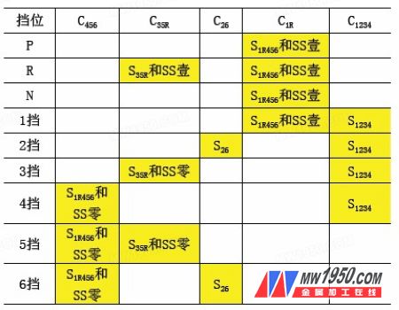
North American 6AT shift logic
The system safety interlock function focuses on the interlocking logic oil circuit of 4, 5, 6 forward gear and 1st gear and R gear. This interlocking oil circuit is especially important for the safety of the vehicle. It is an interlocking function between the high-speed forward gear and the first gear and the reverse gear in the hydraulic shifting system to ensure that the vehicle is even at high speed. There is a problem in the system, and there is no possibility of sudden deceleration or reverse gear, and the correct operation of the first gear and the reverse gear is also guaranteed.
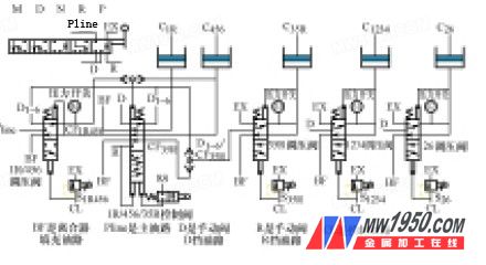
figure 1
As shown in Figure 1, the system adopts four interlocking relationships at the same time, which is the most typical security interlock system. In the figure, in order to specifically study the logic of the shift safety interlock, other unrelated oil circuits are deleted.
First, the PRND manual valve separates the D and R oil lines to ensure that the two oil lines cannot be connected to the system pressure Pline at the same time. When the manual valve is in the R position, the D oil circuit is pressure relief, the R oil circuit is high pressure, C1234 and C26 are connected to the pressure relief oil circuit, and it is impossible to engage; when the manual valve is in the D position, the D oil circuit is high pressure, R oil The road is pressure relief, C1234 and C26 are connected to the pressure relief oil circuit, and it is impossible to join.
For more details, please refer to "Modern Parts", Issue 4, 2013
Linear Floor Drain,Stainless Steel Linear Floor Drain,Linear Shower Floor Trap,Linear Bathroom Channel Drain
Kaiping City Jinqiang Hardware Products Co.,Ltd , https://www.jqfloordrain.com