
I have seen the previous discussion about broken taps. They are all about the selection, tap material, tap quality, and even the cup-type method of testing the tool with a free-fall method after throwing it to the sky for five meters. It is very disgusting. The knife is still judged by personal feelings. Therefore, there is this article.
This paper focuses on the influence of equipment and parts systems on the problem of broken taps and the application analysis of various tapping shanks, including the causes of equipment and the problem of broken cones caused by the displacement and deformation of the fixture and workpiece system. I hope that through this article, we can improve the impact of system problems on processing operations, play a bypass role, increase the understanding of the entire fixture, parts, equipment systems, improve the stability of processing, reduce the cost of a single piece, improve processing efficiency.
1. Equipment requirements for rigid shank mounting tap processing thread
The machining center involves the matching problem between the spindle and the Z-axis when machining the threaded hole. The general tapping function, the spindle speed and the Z-axis feed are independently controlled, so the actual synchronization accuracy will still be different: The deviation between the feed per revolution and the theoretical value is the synchronization accuracy error. The larger the error, the larger the axial component force is generated. For the accuracy of the product, the deviation of the medium diameter value may be caused; In terms of taps, it is almost a prelude to breaking the tap.
2, the meaning of device synchronization function and detection adjustment frequency
It is theoretically feasible to use a tap to machine the thread in a rigid mode on a CNC machine, but the actual control system error is an important cause of the failure.include:
1. Equipment system factors: set equipment speed, axial accuracy (verticality, rotating shaft, C-axis), mechanical system condition of the equipment;
2. The factors of the thread cutter: the pitch tolerance of the tool and the change of the machining depth of the thread cutter will also aggravate the axial force change caused by the error.And even after careful debugging by the professional, the wear and tear of the equipment will produce the same error as the system. In order to better eliminate the synchronization error, it can be better stabilized by adjusting once every six months to understand the change of the synchronization error of the equipment. Cycle regularity establishes equipment maintenance plans to eliminate the fundamental changes in tap fracture problems.
3, (micro-floating) synchronous tool holder use conditions and effects
In the current situation of large-scale use of CNC equipment, most of the equipment will have relatively good working precision, but the equipment and fixture system will have a slight deformation after all, resulting in the rigid tool holder not suitable for working conditions, using a small floating handle; Under normal circumstances, the synchronous shank processing thread will be more rigid than the tapping: 1, (in the range of micro adjustment) can greatly reduce the machine load to 1/10 of the ordinary tapping shank; 2. Maintain the accuracy of the machine spindle And life (especially large thread processing equipment); 3, improve the quality of thread processing, can use high processing parameters, processing efficiency is higher.
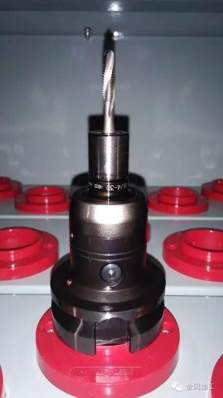
Micro floating handle
4, the application range of floating tool holder
The movable shank is generally divided into two structures: 1. Axial floating shank: According to the processing range, the axial floating range is from 5 to 16.5 mm and 7 to 23.5 mm. For the detection of some floating shanks, it can produce an angular float of 0.1° or more. 2. Radial floating shank: This is a shank commonly used for multi-axis machine tools and automatic transmission lines; it is divided into radial floating values ​​from 0.08 to 1.4 to 2.5 mm depending on the processing diameter range. However, this holder has no axial floating function. The floating tool holder has vibration problems at high speed, and high machining parameters cannot be used. The floating tool handle compression amount will limit the stability of the depth precision of the thread processing, and the thread with high precision hole depth should be carefully considered.
There are five kinds of applicable conditions: 1. The spindle rotation precision is good, but the Z-axis movement has a slight deviation; 2. The Z-axis movement accuracy is good, but the spindle rotation accuracy has errors; 3. The spindle rotation and the Z-axis movement synchronization function have Error; 4, the workpiece-clamp system has a slight variation in the processing (including 1, the rotation is divided into the rotation of the workpiece and the rotation accuracy of the four axes; 2, the X, Y axis of the workpiece is loosely small; 3, the elastic deformation of the workpiece ); 5, the synthesis of the above issues.
The elastic deformation of the workpiece, the elastic deformation of many workpieces can only be detected during processing. When the machining is completed, it can not be detected by the plane measurement method. The straightness of the inner wall of the bottom hole must be detected by the lever table after processing. The "min" error, and this error is not necessarily the performance of the micro-floating handle. It can be seen that the fifth situation is the most complicated and also the source of the more concealed problems.
The floating shank cannot be mounted directly on the tap. Instead, a collet is installed. The collet is divided into an adjustable torque collet and a non-adjusting collet.
5, fixed (adjustable) torque chuck with floating shank application and precautions
A fixed torque structure is added to the quick change chuck to become a fixed torque chuck. If the quick-change chuck without adjustment is installed, there is no torque protection function, only the function of the tool holder and the quick change function.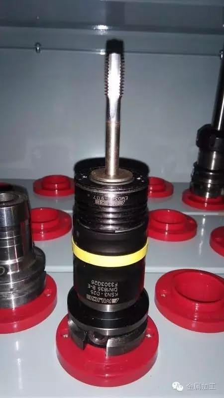
When the adjustable torque chuck is used, when the torque is too large, the spindle and the shank rotate, and the portion of the chuck connected to the tap and the tap do not rotate, preventing the excessive torque from breaking the tap; the axial movement of the spindle is performed by the floating shank The floating amount is eliminated. Each brand of adjustable torque chuck adjustment device is basically similar, but it must be tested after adjustment to ensure that it matches the processing environment conditions, otherwise there will be a broken wire cone or insufficient depth of the batch thread. Because of the friction mechanism inside, such chucks are recommended to be spare one.
Usually in this case, the tap life of the synchronous tapping or floating tapping system is longer than when the rigid tapping is used directly when the system is poorly rigid.
6, data analysis and practice cases
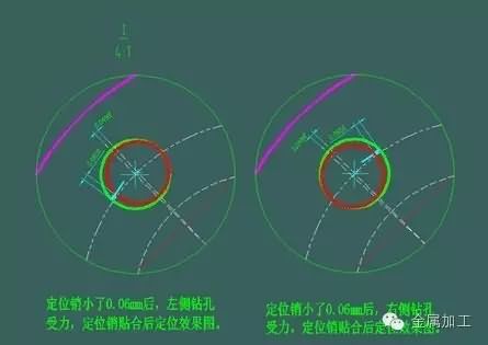
A working condition can be assumed to aid analysis.As shown in the figure, the positioning axis of the part is φ50, the indexing circle of the positioning pin is φ75, and the diameter of the positioning pin is φ13. Only when the positioning pin is worn by 0.06mm, the two ends are machined at 100 lengths. Threaded holes, threaded bottom hole axis may have a maximum error of ±0.05°, and each hole may have an error of 0.026 mm;
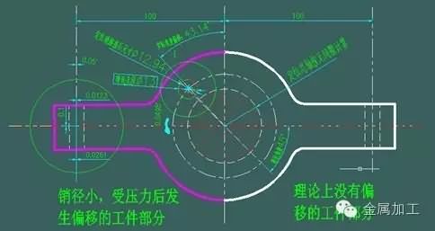
Illustration: When two clamping pins are used, when the clamping force is insufficient or the workpiece is elastically deformed during machining, the φ13 positioning pin with a diameter of 75 mm is smaller than 0.06 mm, and the plane sinking displacement is 0.1 mm. The maximum offset angle of the hole at the 100mm axis is 0.05°From the simulation results shown in the figure, it can be found that when the clamping system is unstable, the micro-shank is not enough to eliminate the error and lose the desired effect, resulting in a broken tap.
Therefore, it is necessary to carry out inspection and verification when deciding whether to use the micro-floating shank; or to design the parts and tooling, the parts and fixtures must consider how to ensure the necessary rigidity.
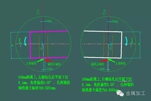
This model is used to understand the contribution of trace changes in the workpiece system to the broken tap. According to EMUGE's research, an excess of 17 μm between the specified position of the tap and the actual position of the machine spindle will result in an axial force of approximately 2800 N; according to this analysis, the 26 μm error produced after the workpiece is deflected by an angle in this model The M10 tap will apply an axial force greater than 2800 N, at which point the probability of the tap breaking will increase a lot; unreliable compression will exacerbate this phenomenon. Of course, it is said that the equipment has an axial feed error, and the resistance of the tap processing will press the workpiece to the state of the drill hole, and there is a tendency to pull the workpiece out. When machining a large threaded bottom hole, the axial force is not very small, the simple feed cutting force will be at least 400N, and the axial force of more than 2800N caused by insufficient synchronization accuracy is enough to overcome the pressing of the workpiece. The power that causes the tap to break.
In this regard, it can be verified in the simplest way: the table is in the vertical direction of the workpiece, the position of the needle is recorded, and the needle is gently lifted, and the other person uses a small pound of a small hammer to gently tap the possible rotation direction of the workpiece, and put it down. The needle, observing the relative movement position of the hands, is the possible range of movement of the workpiece, and calculating the angular deviation of the hole system, so that the type of the tool holder can be used. The wear of the locating pin is a normal phenomenon, so the wear replacement standard of the locating pin is appropriately improved, the possible deflection angle of the workpiece is controlled, and the phenomenon of the broken tap can be improved. To this end, I designed a gapless locating pin that can zero the actual clearance between the locating pin and the workpiece, and repeat the positioning accuracy to within 0.02 mm.
In fact, there are still many factors that are not drawn in the figure, including 1. the gap between the positioning sleeve and the positioning rod, which will magnify the angular error in the above figure; 2. The elongated workpiece (accurately speaking should be Pieces with poor rigidity), the up and down yaw during machining, are dynamically changing, and the actual error may be much larger than the deviation after machining. 3, the gap between the X and Y of the equipment to the screw, because in many cases there will be clearance compensation, the actual machining will have a gap range of movement, resulting in the actual different axes, and this gap with a simple table method, Basically, it can't be detected; 4. The yaw of the spindle in the X and Y directions on the guide rail, the main shaft is also to be moved. There must be a gap to move. When the contact surface is worn, the deviation caused by the gap is small. Tap processing is also a serious flaw that cannot be ignored.
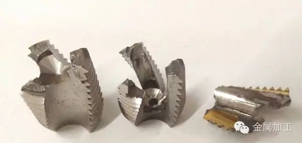
In the case of a rigid tapping broken tap problem, the search for the cause was quite troublesome, the rigidity of the equipment system and the parts were all checked, and the cause was not found at all; later, it was noticed that the broken tap always had a chip cutting of the cutting edge. As shown in the figure below; continue to observe that the over-center plane boring tool before the hole machining process has a convex tip, and the subsequent slender shank attachment (part interference can not change the structure) of the drill threaded bottom hole will be this convex The tip was removed and could not be visually inspected. The cusp is first contacted with the drill tip, causing the axis of the hole to be offset after drilling, and the result of the offset of the hole axis (the difference in straightness) is that the cutting resistance of the tap is sharply increased, and the tap is frequently irregular, because of the shape of the cusp and The height is also irregular; according to this problem, the improvement method is to replace the new boring tool which can ensure the center without the cusp. After eliminating the cusp before the drilling, the broken tap phenomenon is reduced by 70%, and the workpiece is confirmed after the calculation. Smaller offsets improve clamping reliability and replace the micro-floating tapping shank to continue to improve the broken taper problem.
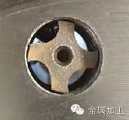
Illustration: The tap breaks at the exit and freezes down
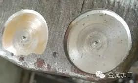
Illustration: The squat plane before drilling has a cusp
7, the conclusion
In summary: the tool clamping system for rigid tapping is usually lower than the tool clamping system for synchronous tapping. The thread precision of synchronous tooling is better than that of floating tapping in high-speed machining, and the thread length is controlled. For precision. There are many types of floating shanks, which can be transferred to the torque-protected chuck. The requirements for equipment and fixtures are low, and the floating range is relatively large. However, it is generally not capable of high-speed machining, and is widely used in special machines and low-precision fixtures and equipment. For high-precision important parts, the tool holder system for wireless transmission technology alarm monitoring can be used.
The history of stone carving begins with the origin of human art. It can be said that there is no art form that is more ancient than stone carving, and there is no art form that is more popular and lasting. The history of stone carving can be traced back to the middle of the Paleolithic Age, which is about 120000 years ago. Since then, stone carvings have been handed down to this day.
Stone Crafts,Wexford Stone Crafts,Natural Stone Crafts,Stepping Stone Crafts
The universe in the stone is great , https://www.zdsarts.com