
Fundamental
1. Calculation model analysis
The fluid in the calculation includes the engine coolant and the lubricating oil. The solid is the bearing body. The two fluids do not touch or fuse with each other, and the movement of the fluid does not cause large deformation of the bearing body, but affects the movement trajectory of the fluid. The unidirectional coupling problem of the fluid, there is heat exchange between the fluid and the bearing body. There is a mutual constraint between the fluid and the solid wall. The thermal boundary condition cannot be given in advance. It is a typical weak coupling problem, that is, there is heat exchange only at the boundary, and the temperature and heat transfer coefficient on the boundary should be part of the calculation result. , not known conditions. A better way to solve this type of problem is to combine the fluid in the cavity with the bearing body to perform fluid-solid coupling calculations to achieve heat transfer between the fluid and the solid wall.
2. Theory of heat transfer
When the fluid flows in the bearing body cavity, a boundary layer is formed at a position close to the wall surface, and the flow rate of the liquid there is very low, almost zero, so the heat exchange between the fluid and the wall surface is mainly heat conduction, and outside the place The form of heat transfer in the area is primarily thermal convection between fluids. The heat transfer q caused by heat conduction can be determined by Fourier's law of heat conduction:
Under normal circumstances, the convective heat transfer amount q of the fluid and wall per unit area per unit time can be determined by Newton's law of heat exchange:
h - heat transfer coefficient, w / (m2 · k);
TW - wall temperature, k;
Tf - fluid temperature, k.
Establishment of a computational model
This study is mainly concerned with the temperature field distribution of the bearing body under the action of coolant and lubricating oil. In order to save computing time and computer resources, these two parts are not included in the calculation model. Considering the actual working process, the high temperature gas in these two parts will have a great influence on the temperature of the bearing body. The temperature at the contact between the two parts and the bearing body is obtained through experimental tests and calculations, and is loaded into the bearing as a boundary condition. Both ends of the body. The contact portion between the turbine casing and the volute and the bearing body exchanges heat in the form of heat conduction, and also considers the heat exchange between the outer surface of the bearing body and the outside air.
1. Processing of geometric models
This research selected a gasoline engine supercharger developed by our company. The cooling form of the bearing body is water circulation cooling. In addition to lubricating the floating bearing, the lubricating oil will also take away part of the heat of the bearing body. The three-dimensional model analyzed should include three parts: the bearing body, the cooling water body and the lubricating oil body. Firstly, a three-dimensional model of the bearing body is constructed in UG, and some functional structures that do not affect the fluid-solid coupling analysis are simplified (such as partial chamfering, positioning holes, etc.). The three-dimensional model of the cooling water body and the lubricating oil body is constructed by the three-dimensional model of the bearing body, and the two fluid models are simplified.
2. Computational model meshing
For the bearing body mesh, this paper adopts a tetrahedral mesh, which is processed by the structural meshing technology of ANSYS, and refines the area that needs local attention; and the network of two fluid parts for cooling water and lubricating oil. The grid is divided into CFD grids, and the boundary layer of the two fluids is specially processed. The grid model is shown in Figure 1 and Figure 3.
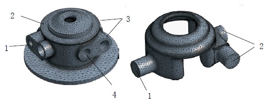
Fig.1 Grid model of bearing bodyFig.2 Grid model of water body
1. Inlet 2. Return port 3. Outlet 4. Inlet 1. Inlet 2. Outlet
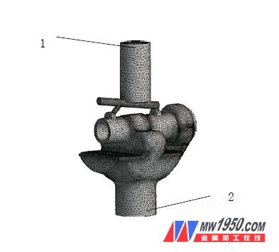
Figure 3 Grid model of the lubricating oil body
1. Oil inlet 2. Return port
Calculation results
In CFX, the fluid-solid coupling calculation is performed with the two-part fluid separately from the bearing body to obtain the surface temperature and thermal convection coefficient of the fluid, and then the thermal convection coefficient calculated in this part is loaded into the bearing corresponding to each part in the form of load. On the surface of the body, a steady-state thermal analysis is performed to obtain the temperature distribution of the entire bearing body. The calculated temperature fields of the two parts of the fluid are shown in Figures 4 and 5, respectively. The temperature distribution of the bearing body obtained by steady state thermal analysis is shown in Fig. 6.
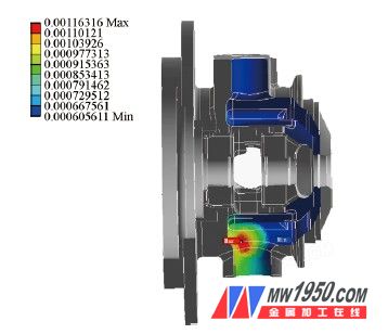
Figure 4 Cooling water body calculated thermal convection coefficient
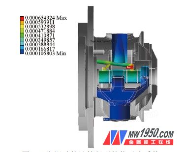
Figure 5 Thermal convection coefficient calculated from the lubricating oil body
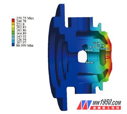
Figure 6 Temperature field distribution of the bearing body
Conclusion
The calculated temperature distribution trend is consistent with the experimental results, which proves that the analytical method used in this paper is feasible. From the calculation of the cloud data, the temperature near the floating bearing and the seal ring is lower than the allowable limit temperature, which proves that the bearing body cooling design is feasible.
HOLLY customized thickness Colorful Rubber Foam product is an environmental protection insulation material with closed cell structure.It is manufactured without the use of CFC'S, HFC'S OR HCFC'S. It is also formaldehyde free, low VOCS, fiber free, dust free and resistant to mold and mildew.
It is used in the automotive and aeronautical industry to make fuel and oil handling hoses, seals, grommets, and self-sealing fuel tanks, since ordinary rubbers cannot be used.It is used in the nuclear industry to make protective gloves. NBR's ability to withstand a range of temperatures from −40 to 108 °C (−40 to 226 °F) makes it an ideal material for aeronautical applications.Nitrile butadiene is also used to create moulded goods, footwear, adhesives, sealants, sponges, expanded foams, and floor mats.
Colorful Rubber Foam,Fireproof Rubber Foam Pipe,Fire-Retardant Insulation Rubber Foam Tube,Fire-Retardant Rubber Foam Tube
Wuxi Holly International Trading Co., Ltd , https://www.hollynbr.com