While in-process sensors are used to control the quality of their processing in many plants, many manufacturers are still very cautious, fearing that these systems will increase their cycle time. However, Renishaw experts say this is very unrealistic. According to the company, measurement and cutting are performed on the same machine, providing many competitive advantages. Therefore, it will become the standard practice of the factory in the future.
The probing system allows manufacturers to automatically monitor, calibrate and provide data during processing without operator intervention. During the operation of the machine, the detection system automatically corrects the manufacturing variables through closed-loop process control, such as operator skill, machine tooling capability, material type and workshop environment, and feeds back the data measured relative to the machine coordinate system to its control. Used for compensation in the machining program.

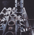
Testing a cylinder block with a contact trigger sensor,
On the automatic line, the workpiece is automatically "buy" in the work cycle.
Mr. Dan Skulan, regional sales manager at Renishaw, explained that the detection system falls into two broad categories: part adjustment installation/inspection and tool adjustment. The adjustment test probe is a contact trigger sensor that is mounted in the spindle or turret of the machine tool and acts like any other tool on the machine. On the other hand, the knife adjustment probe can be a non-contact laser or a contact trigger sensor mounted on a machine table or on a carriage other than the machine operating area.
Closed-loop control
For closed-loop control, adjust and inspect the probe to monitor the size and position of the critical point at some stage, such as before finishing, by trigger signal generated when the sensor ball touches the surface of the part to measure the reference point. In CAD/CAM applications, these have standard rules.
When the machine receives this signal, the machine has a "fast phase" of data point positioning and orientation based on the axial position compared to the programmed position. The probing software then automatically updates the tool workpiece offset record in the controller to keep the part within tolerance or an alarm to inform the operator that the part is out of tolerance.
“Process control like this is the first to be adopted in the aerospace industry,†Skulan said. "For example, a company may have invested $40,000 and a lot of processing time on a casting. If the process is too bad in any way and can't be processed, it will be abandoned. Needless to say, this is not very cost-effective."

On the profiles that make up the Boeing 747 barrel, the formed sheet metal parts are measured using a probing system to determine the optimum position for the drilling assembly holes.
Skulan said that during machining, the shop cuts parts at the first pass, for example, more than 0.003 or 0.004 inches. Then the probe captures the size of the part and automatically adjusts the offset to ensure that the cut material can be cut off to ensure that the part is within tolerance.
In addition to providing closed-loop control, machine tool detectors improve machining efficiency and accuracy at almost every other stage of the process, says Dave Bozich, product manager for machine tools at Renishaw:
Identifying workpieces: For automated part machining, the detector determines if the part is properly installed and calls the correct NC program.
Adjusting the installation: The detector is used to position the part and establish the coordinate system of the workpiece, reducing the adjustment and installation time to only a few seconds, eliminating the non-production process and increasing the productivity of the machine. Adjusting the mounting detector also eliminates the need for complicated and expensive positioning fixtures, which is a big advantage. Because the detector "finds" the part, the fixture only needs to clamp it.
Tool adjustment: The tool adjustment automatically adjusts the tool length and diameter during machine operation and identifies broken tools. The knife adjustment detector is an economical solution for checking tool geometry and tool conditions on the machine.
Final inspection and purchase: Using the detector on the machine tool, the workshop can still “buy†a part while still on the fixture, which greatly shortens the processing time. It eliminates the additional process, time and expense of unloading parts, transporting parts to the CMM, and then clamping, taking into account thermal effects and establishing data points before measurement.
First piece inspection: With Renishaw's Master Artifact-comparison Technology, the detector enables the first piece to be tested without seams and automatically, verifying that the part has reached the dimensions. The detection eliminates the lag of manual inspection and the time of loss of the spindle, especially when the operator needs to remove the part for inspection and then install the compensation for cutting.

Contact trigger detector adjusts a casting for processing
Accurate contact
The structure of the contact trigger detector can withstand difficult processing environments. The detector consists of a probe, a detector body equipped with trigger sensing electronics, a probe, signal transmission technology, and a machine/controller interface. The probe comprises a shaft made of stainless steel, tungsten carbide, ceramic or carbon fiber and a contact ball made of hard metal or special material such as ruby, zirconium or silicon nitride (may also be non-spherical in other shapes) On the shaft.
Designed for contact trigger detectors for small vertical machining centers and high-speed machine tools, with a motion-resistant sensor that combines mechanical and electrical sensing capabilities in one mechanism for contact detectors for high precision and complex parts Strain sensing technology. A silicon strain gauge is used to measure the force transmitted through the probe without a contact point like a switch. This is more precise than the contacts because it produces equal triggering forces in all directions.
Transmitting signal
After the contact detector triggers a signal, the signal is transmitted to the receiver, usually to the machine's controller. In practical applications, where the receiver is remote from the detector and cannot be connected to the electrical line, the signal transmitted from the detector must pass through the wireless system.
An inductive delivery system that digitizes sensor measurements. Inductive systems do not require a battery and can deliver signals across a small air gap in an environment with oil, coolant, metal chips and other contaminants. Inductive systems require precise positioning of their transmission components, making them suitable for installation in original equipment manufacturers.

Graphite electrode – used to machine the pits on the die – to receive the final inspection on the machine
Another wireless system is optional, or infrared, which transmits a trigger signal through an infrared beam. Battery-powered detectors can transmit signals at 360o—about 20 feet (short to medium)—that are interference-free, including reflected signals. The infrared system is simple, easy to install on new machines, and easy to retrofit old machines without probing.
For large machine tools and parts with complex geometries that require internal features, the radio transmission system can transmit 49 feet for applications where there is no direct line of sight between the transmitter and receiver. Renishaw's special radio technology uses automatic frequency reflection, and the signal continues to move around different frequencies to find the turn-on frequency. This prevents jamming of transport and dead spots and ensures data integrity.
Illuminate
A non-contact laser sensor transmits a laser beam between the conveyor and the receiver. When the cutting tool intersects this beam, it triggers the signal. The laser tool holder automatically checks the length, diameter and tool shape of the tool, eliminating the need to manually adjust the block gauge and size the part with a micrometer. In addition, because the tool is adjusted during rotation, there is no radial runout or insert height deviation.
According to Renishaw, the conventional method of adjusting the tool length with a non-contact system involves only the operator moving the tool, intersecting the beam anywhere, and executing a simple G code. This will automatically update the offset of the current tool.
The laser sensor can also be used to quickly and “in flight†the damaged tool in the cycle. (Although the contact type cutter can also check the broken tool, the tool must be brought into contact with the tool setting tool.) The trigger signal or the identification tool is damaged, so the operator can change the tool; or flip the excess tool to make the machining Continue now. Therefore, damaging a tool no longer causes the workshop to discard a batch of parts.

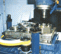
In this two-tray vertical machining center, the laser sensor performs a quick adjustment.
The sensor's transmitter and receiver are mounted outside the work area so that the tool can be inspected during machining.
Artifact comparison method
The Artifact is a part that is made of the same material as the part to be machined and used for the proofreading. The part may not have all the features of the finished product, but it certainly has key measurement points.
Renishaw first measured the part on a coordinate measuring machine in the laboratory, which was calibrated to international standards that could be followed, such as the US NIST or the National Physical Laboratory (NPL) standard.
The company also inspects its machine tools to ensure that it meets standards such as ISO or ASME, both of which require bat and laser calibration checks. Skulan said it is important to note that these standards do not specify the accuracy that the machine must meet, they do not determine the accuracy that must be met (its processing capability).
The company then positioned and clamped the part. The spindle-mounted detector measures the dimensions of the various parts of the part throughout the machining cycle for comparison with the programmed part and then compensates for the difference when machining the part.
The part comparison method is particularly effective for capturing angles and transient thermal errors, which cannot be compensated by laser. According to the company, manufacturers can apply this technology to almost any machining center, keeping tolerances close to machine repeatability standards and compensating for thermal effects. The part comparison method can also be used for the inspection of the first piece and the last part.
IS Type Single-Stage Centrifugal Pump
Single-Stage Centrifugal Pump,Horizontal Single-Stage Centrifugal Pump,Single-Stage Centrifugal Water Pump
Shenyang pump products sales co., LTD , https://www.syipsc.com
