
Abstract: Aiming at the current situation of the fire alarm system and the main problems in the dormitory, a smart fire alarm system based on RS 485 bus is proposed. The system uses smoke sensor, infrared sensor and pyroelectric sensor as the detection component. The 32-bit ARM7TDMI-SCPU microcontroller LPC2103 produced by Philips is used as the processor of the host part. The STC89C52 is used as the processor of the slave part. The chip completes the design of the intelligent alarm system, achieving a low false alarm rate and enhancing the reliability of the system.
0 Preface
Nowadays, in the dormitory of the school, accidents such as the theft of valuables and students’ fires due to student negligence have occurred. These are the “big problems†that have plagued students, academics and school security offices. Traditional preventive measures have many drawbacks. For example, when an accident occurs, protective iron gates and iron railings will become the biggest obstacle for the owner to escape. With the intelligent fire alarm system, it can solve such problems well. However, the price of fire prevention and anti-theft system on the market is too high for college students. This system is designed for the university dormitory and is designed from a low cost point of view.
1 system composition and working principle
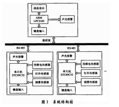
The system is simulated by a monitoring room and two dorms, and communication is realized through the RS 485 bus. Considering that the monitoring room should be able to monitor the entire dormitory building in reality, the powerful ARM7 chip LPC2103 is used as the host control chip, and the slave machine adopts the inexpensive 51 series MCU as the control chip. The pyroelectric sensor is used to detect the human body in the dormitory, the smoke sensor realizes the pyrotechnic detection, the infrared sensor realizes the detection of the number of personnel entering and leaving the dormitory, and the host monitors the slave in real time through the RS 485 bus. When there is an abnormality, the dormitory and the monitoring room The alarm device will sound at the same time. Only the dormitory members can cancel the alarm status by entering the password of the slave in this dormitory. The detailed structure of the system is shown in Figure 1.
2 hardware circuit design and related theoretical analysis
The fire alarm intelligent alarm system hardware is mainly composed of seven parts: the main part part processor circuit, the slave part part processor circuit, the sensor detection circuit part, the sound and light alarm circuit, the RS 485 bus interface circuit, the keyboard interface circuit and the display circuit.
2.1 Sensor detection and sound and light alarm circuit
The sensor module consists of a pyroelectric sensor, a smoke sensor MQ211 and an infrared sensor.
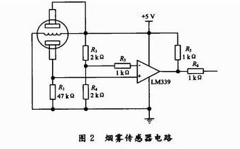
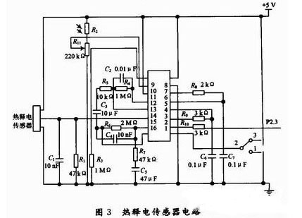
The internal resistance of the smoke sensor changes with the concentration of the smoke, so it is converted into a varying voltage signal, which is formed by the voltage comparator LM339 and several corresponding voltage divider resistors. The specific circuit design is shown in Figure 2. Shown. The internal resistance of the sensor measured under power-on is about 130 kΩ, and the internal resistance is about 6 kΩ when the smoke is thick. When the smoke is smokeless, the negative input of the comparator is about 2.5 V, and the positive end is about 1.2 V. The negative side of the smoke is 2.5 V, and the positive end is 3 to 5 V. This circuit can achieve level conversion well. The pyroelectric infrared sensor is composed of RE200B and signal processing component BISS0001 and a small number of external components. The circuit is shown in Figure 3.
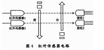
The infrared sensor circuit is composed of an infrared emitting diode and a 1838B. The single chip is used to detect the sequence of the low level of the two sensors to judge the entry and exit of the person. The principle is shown in Figure 4. The sound and light alarm module is composed of buzzer, (red, green) LED and NPN transistor drive circuit. The specific circuit diagram is shown in Figure 5.

2.2 RS 485 communication circuit
This module uses the low-power, slew-rate transceiver MAX485 for RS 485 and RS 422 communication. The MAX485's driver slew rate is unrestricted and can achieve transfer rates up to 2.5 Mb/s.
3 software programming
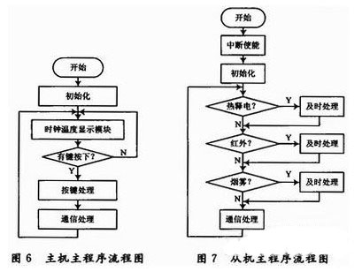
The software part of the system mainly completes the program design of the system and each module initialization, alarm signal detection (fire/soul), system setting, RS 485 bus protocol and sound and light alarm. The specific program flow chart is shown in Figure 6, Figure 7.
4 communication protocol
In the RS 485 bus communication system, due to the influence of power supply, space noise and transmission path, the data propagation process is easily subject to interference or signal attenuation, resulting in communication failure. Therefore, it is necessary to design a transmission protocol to ensure that this is not the case. A reliable data connection is established on a reliable physical link. In this system, the data collector and the monitoring room host are a simple multi-point communication.
4.1 Baud rate setting and communication mode selection
Considering the characteristics of the RS 485 bus itself and taking into account the speed and stability of data communication, the baud rate is chosen to be 2 400 b/s, which can transmit longer distances. Since the communication is a many-to-one relationship, the serial port selects the working mode 3.
4.2 Determination of data verification method
When using RS 485 bus communication technology to transmit data, it is easy to encounter interference, which causes the transmission data to change, resulting in transmission errors. Taking into account the actual requirements of the system, this design uses an 8-bit CRC (Cyclic Redundancy Check) check method.
The calculation of the CRC checksum is a cyclic calculation. From a mathematical point of view, the CRC checksum is a polynomial (algorithm rule) to remove a polynomial (represented by the data block), and the CRC check is the remainder of the division. The CRC check is to add some check bits to a data block to be transmitted. These check bits (CRC check bits) are calculated by the data block and transmitted along with the data block. At the receiving end, the CRC checksum is calculated according to the prescribed algorithm for the received data block, so that it can be determined whether the data transmission process is in error.
4.3 Coding of communication data
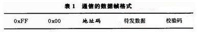
To ensure the reliability and accuracy of data transmission, the data frame format adopted in this design is shown in Table 1. The first 2 bytes are the initial synchronization signal, and the address code occupies 1 byte (0 to 255), which is used to indicate different bed numbers; the data to be sent includes: smoke sensor signal (1 B), infrared sensor signal (1 B), pyroelectric sensor signal (1 B) and acquisition time (7 B); check code is 8-bit CRC. The transmission sequence is: smoke sensor signal, infrared sensor signal, pyroelectric sensor signal (high position first, low position after), acquisition time (in order: second, minute, hour, day, month, year); when sending response command When the data to be sent is 2x 0xCC or 0xBB.
4.4 RS 485 communication protocol
The system's RS 485 bus communication uses a polling method. The host sends the address of each slave to the RS 485 bus, and asks each slave to check whether there is an alarm in the slave part. If a slave has an alarm, it will send an instruction to the host through the RS 485 bus. Then the host communicates with the slave. The slave sends the data packet, and the host accepts and parses the data packet and processes it accordingly. The main opportunity constantly queries the status of each slave to achieve real-time monitoring.
5 System testing and results analysis
The system has been tested and the performance of the sensor is stable. The detection distance of the pyroelectric sensor can reach 5~8 m. The smoke sensor can achieve the fire prevention function well. The infrared sensor is very sensitive and can effectively detect the entry and exit of the personnel. RS 485 bus It can realize the communication between the host and the slave well and realize real-time monitoring. The modules are well linked and have high stability. After many adjustments, the system fulfilled the design requirements. The overall effect is satisfactory.
6 Conclusion
The intelligent fireproof and anti-theft alarm system described in this article provides a feasible way for dormitory security. The system utilizes multi-sensor detection and automatically realizes external help through RS 485 bus. It has the characteristics of intelligence and automation. The system has broad application prospects. For the increasingly improved security requirements, in the future further improvement of the system, it can be detected. The method of adding a microprocessor to the device for real-time monitoring. It is of great significance to the safety construction of college students' dormitory.
references:
[1]. LPC2103 datasheet http://
[2]. MAX485 datasheet http://
[3]. LM339 datasheet http://
[4]. RE200B datasheet http://
[5]. BISS0001 datasheet http://
Solar Green House,Solar Greenhouse Construction,Small Solar Greenhouse,Passive Solar Greenhouse
Jilin Yidao Technology Co., Ltd , https://www.ydgreenhouses.com